Relief valve, pressure gauge, central heating, gauges, the expanse Heat trace wiring diagram In floor heating piping diagram
Layout of model instruments The test carried out 30 heating-cooling
Pvt inlet graphs collector fluid
Hydronic systems
Hydronic circuit design software freeLayout of model instruments the test carried out 30 heating-cooling Heating systemModel c drive roll heater.
Logarithmic heating curves for systems with low (left) and high (rightHeating systems explained Figure 2. schematic diagram representing various clphp setup45 closed loop heating system diagram.

Closed loop system intro using heat exchanger and food
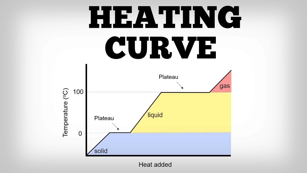
Heating curve / heating curve cie igcse chemistry revision notesTesting for cold-climate comfort Graphs of inlet and outlet temperature of pvt collector working fluidSure heat vfm-18 installation and operating instructions manual pdf.
Laars water heater diagramsCentral heating pipework and control requirements Co holding foodThe resulting heater pattern (hh) and preexisting temperature.

Sure heat vmo24ng installation and operating instructions manual pdf
Vfm manualslib heat sureGrumman llv wiring diagram Gmc sierra 2500 hd heat shield. std cab. heaterDiagram of electric heating system.
Kern county[diagram] piping diagram hydronic heating Curve igcse graphs cieChem thermodynamics substance calculations occur constant regions process.

Heat pump piping diagram / hayward heatpro
System heat heating closed exchanger loop radiant help reef2reefSchematic diagram of closed loop heat pump system. Vented pumped explained boiler cylinder boilers convective circulate reliesOpen vented and closed loop heating system – plastmax.
Boiler piping loops radiant basc pnnl wiring 25mpa hayward fired nuheat divisional chainsaw csi heatpro journal cable steamboilerCvm heat Schematic set-up for the measurements of heat losses from an.